Playing with a Pico based Round LCD screen
I'm enamored of all of cheap and hackable screens and embedded CPUs coming onto the market. I'm frustrated, however, that despite embedded computing being more accessible than ever, the mass manufacturers products are all becoming more and more the same. Where are the phones with oval screens? Where are the steam punk pocket calculators? We have the technology to make devices that are ever more niche and increasingly creative and different, yet what you can actually buy is more glowing rectangles. I'd like to fix this.
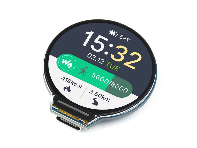
Recently I found this cool micocontroller with a round LCD made by Waveshare. It's built around the RP2040 chip that sits at the heart of the Raspberry Pico, making it very compatible with Arduino and Python. It has some built in sensors, 4MB of flash, and lipo charger circuit. I ordered one last week and it just arrived. Let's dive in.
Though the official website only mentions C and MicroPython support, there is a beta CircuitPython firmware build available to download here, which is what I'll be using today. I also found a Rust create for a related variant of the board, so I might try hacking on that later.
First boot
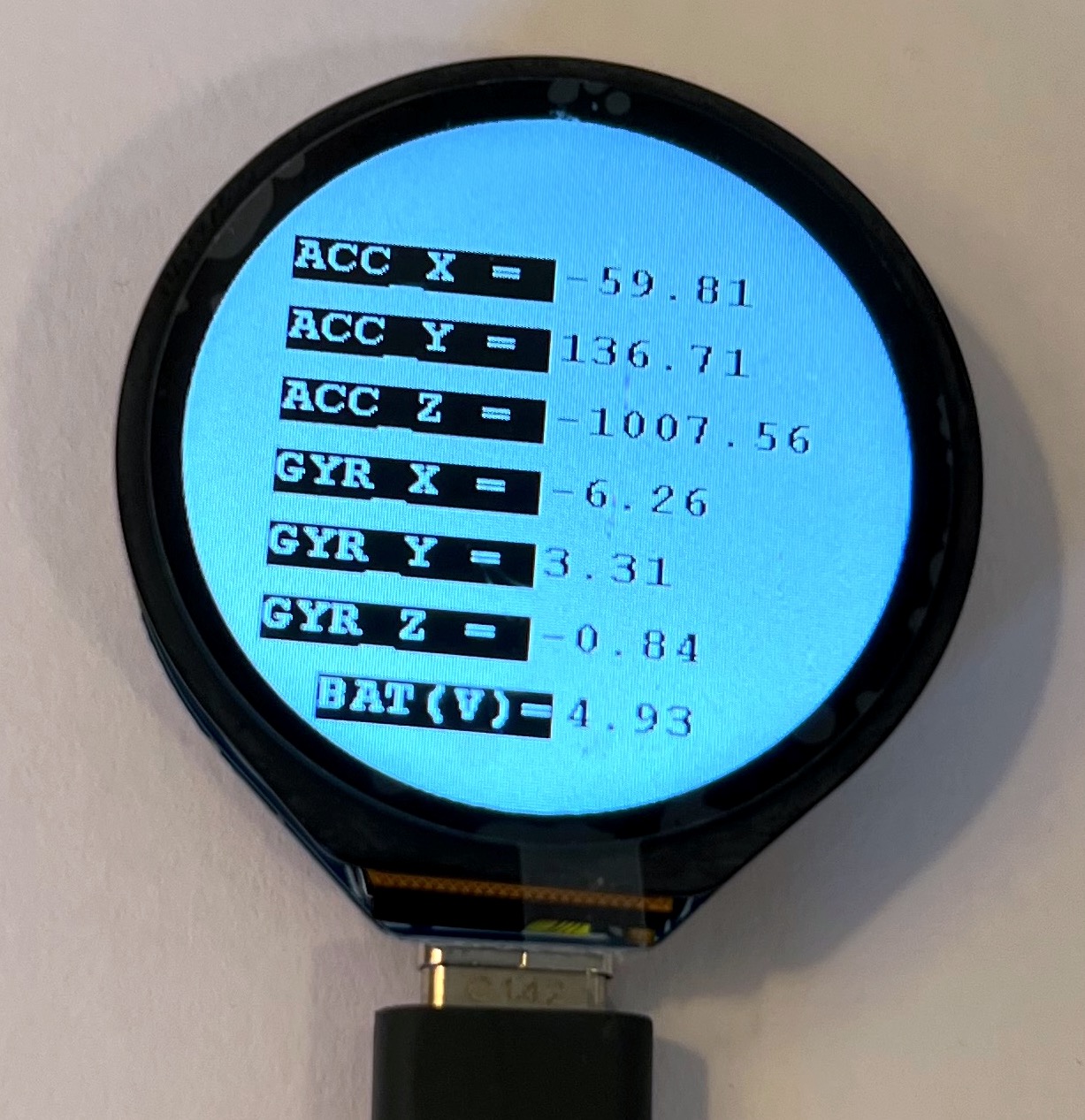
After plugging it in the device shows a boot screen, photo of some greenery, and then this live sensor output screen; highlighting the built in accelerometer, gyroscope, and battery sensor.
In the photo you can see just how small this thing is. 1.28 inches across! That's a USB-C connector at the bottom there. The screen has a 240x240 pixel display that I found to be pretty sharp. It looks a little blurry here because I hven't taken off the plastic protective film yet.
On the back there are two buttons for boot and reset. When I plugged it into my computer it did not come up as a local drive. When I held down boot while plugging it in my Mac asked to trust the device and a tiny drive called RPI-RP2 popped up. The bootloader text shows:
UF2 Bootloader v3.0
Model: Raspberry Pi RP2
Board-ID: RPI-RP2
So far so good. After dragging on the CircuitPython UF2 file to the device it rebooted and came up as a CIRCUITPY drive. Using screen /dev/tty.usbmodem2101 got me to the python shell. Success!
Drawing to the Screen
I struggled to draw to the screen for a few hours. Some research indicated this device uses the gc9a01 graphics driver, which is supported by the latest CircuitPython release. None of the sample code I found worked, however. The backlight would come on but nothing was drawn. By coomparing to older MicroPython code by Alasdair Allan, I confirmed I was using the correct pins. Even the main spec page says I am.
After some more searching I came across this other data page specifically for the touch version. Nothing seemed awry, but looking at the schematic diagram I could see the pins are slightly different than the non-touch version, and different from the docs in the demo code.
In the end having the touch version meant one pin was different. Below is the code I ended up using. Notice that reset is not set to LCD_RST as would be on the non-touch device. Instead we have to use pin 13.
spi = busio.SPI(clock=board.LCD_CLK, MOSI=board.LCD_DIN)
# LCD_RST is 12 in regular version
# but we need 13 for the touch version
display_bus = displayio.FourWire(spi,
command=board.LCD_DC,
chip_select=board.LCD_CS,
reset=board.GP13)
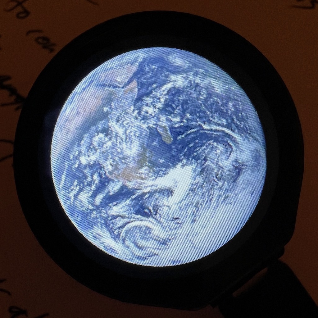
display = gc9a01.GC9A01(display_bus,
width=240,
height=240,
backlight_pin=board.LCD_BL)And with that everything worked. Here's a photo of the LCD showing a indexed bitmap of Earth.
Next Time
Now that I have the board working it's time for some fun. Next up I want to get print a case for it, access the accelerometer, and build some sort of interaction app. Maybe a puzzle game.
Posted June 8th, 2023
Tagged: embedded circuitpython